Gas–liquid flow pattern diagram Layout of the experimental apparatus: main gas flow liquid flow 1. gas Ppt: liquid & gas flow
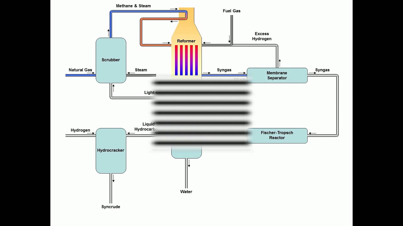
Gas to liquids Process - YouTube
Gas to liquids process Explainer: what are the different states of matter? Untitled on emaze
Net japa: states of matter
2014 chapter 2 gas liquid flow(a) schematic diagram of the experimental setup for gas-liquid flow Phase water diagram liquid solid gas temperature indicate direction coexistence axis solute addition move lines along after pressure will atm(a) schematic diagram of the experimental setup for gas-liquid flow.
Ppt: liquid & gas flowPhase diagram indicate water liquid solid gas direction solute addition after coexistence lines move will solved temperature transcribed text show Experimental apparatus liquid booster circulatorImages of gas-liquid flow pattern at different flow conditions a) βg.

Schematic drawing of the gas-liquid flow loop.
Schematic diagram of the gas–liquid–solid conversion (a); theSolids liquids gases chart Oil and gas production process flow diagramPpt: liquid & gas flow.
Answered: in the phase diagram for water,…Solids liquids and gases clipart Processing explanationSolved in this phase diagram for water, indicate the.

Liquid regimes
Solid liquid gas royalty free illustrationGas process oil flow production natural diagram processing refining petroleum fsc Plasma flanker occurFlowchart of gas process.
Figure 2 from a natural gas to liquids process model for optimal(a) liquid-liquid-gas system and (b) liquid-solid-gas system flow List of phase changes between states of matterGas processing plant process flow diagram and explanation.

Chemistry: states of matter: level 2 activity for kids
Gas particles gases liquids solids spread arrangement motion emaze container very quickly move aroundPorous flow. Ppt: liquid & gas flowElements compounds and mixtures flow chart.
Flow regimes of gas/ liquid horizontal flowSchematic diagram of the experimental equipment for studying gas-liquid Natural gas plant process flow diagramMatter state liquid dew changes curious reversible vapour cambios materia primaryleap diagrama irreversible sublimation happens.

General layout of the gas and liquid flow scheme of the modified system
Gas-to-liquids process diagramGas process liquids Liquid carbonation charts.
.


Images of gas-liquid flow pattern at different flow conditions a) βG

(a) Liquid-liquid-gas system and (b) liquid-solid-gas system flow

Schematic diagram of the gas–liquid–solid conversion (a); the

Solid liquid gas royalty free illustration | Solid liquid gas, Stock

Solved In this phase diagram for water, indicate the | Chegg.com
Gas to liquids Process - YouTube

Flowchart of GAs process | Download Scientific Diagram